Run-time Assurance
The Run-time Assurance Module (RAM) is the heart of the Supervisor. This module is responsible for calculating the appropriate command to send to the robot to stay “safe” based on available system information. It is built as 3 main components:
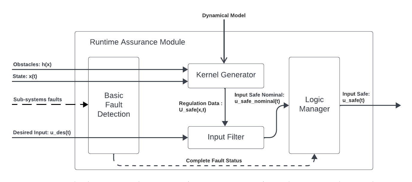
- The Kernel Generator uses
an appropriate dynamical system Model,
the system’s current state,
the predicted environment state, and
a set of possible actions that can be taken to keep the system safe
to calculate a set of “safe” commands that can be applied to the system. This set of actions is then passed to the input filter.
The Input Filter selects the command that is a closest to the desired command sent by the autonomy stack from the set of safe commands produced by the Kernel Generator.
Fault Manager detects basic faults (e.g. signal timeouts) from the signals sent by the autonomy stack to the RAM and implements appropriate stopping strategies.
Dynamical Model
In order for the kernel generator to determine the set of safe commands that can be sent to the robot, it must be able to quantify how the robot will behave when it receives a particular command. This is done through the use of a dynamical model.
A dynamical model of a robot is defined by 6 items:
A state vector \(x \in \mathbb{R}^\text{nx}\) representing the set of relevant physical quantities for that robot (position, orientation, velocity …).
An input vector \(u \in \mathbb{R}^\text{nu}\) representing the set of relevant cyber-physical quantities for that robot that can be controlled directly (motor torque, desired velocity, desired rotation rate …).
A set of equations of motion in vectorized form \(\dot{x} = f(x,u)\) that describe how the state of the robot evolves over time when it receives a particular input. These equations of motions will often be parameterized by known fixed quantities \(p \in \mathbb{R}^\text{np}\) called model parameters (mass, distance between wheels, maximum/minmum accelerations, maximum turn rates,…),i.e. \(\dot{x} = f(x,u,p)\)
A set of input constraints \(U \subseteq \mathbb{R}^\text{nu}\) that affect the set of all possible inputs that can be sent to the robot.
A state domain set \(X \subseteq \mathbb{R}^\text{nx}\) that represents the domain for which the equations of motion are valid, particularly with respect to the process covariance matrix.
A process noise covariance matrix which represents the probability distribution of the actual \(\dot{x}\) around the predicted value by \(f(x,u)\) for all given \(x \in X\) and \(u \in U\).
The Supervisor currently ships with 3 supported dynamical models:
Unicycle
This model is a 3-state, 2-input model that describes the movement of a robot evolving on SE2 (2D planar space with orientation), where control is available for longitudinal and angular speeds directly. This model is particularly well suited for differential drive robots with fast acceleration and deceleration.
Model state: \(\left[x,y,\theta \right]\)
Model input: \(\left[ v_x, \omega \right]\)
Model parameters: None
Equations of motion: \(\begin{cases} \dot{x} = v_x \cos(\theta) \\ \dot{y} = v_x \sin(\theta) \\ \dot{\theta} = \omega \end{cases}\)
State domain: \(\mathbb{R}^3\)
Input constraints: User defined hyperbox in \(\mathbb{R}^2\)
Process noise covariance matrix: Identity matrix
Omnidirectional
This model is a 3-state, 3-input model that describes the movement of a robot evolving on SE2 (2D planar space with orientation) where control is available for longitudinal, lateral, and angular rates directly. This model is particularly well suited for mobile robots with omni wheels, quadrupeds, and surface vessels with fast acceleration and deceleration.
Model state: \(\left[x,y,\theta \right]\)
Model input: \(\left[ v_x, v_y, \omega \right]\)
Model parameters: None
Equations of motion: \(\begin{cases} \dot{x} = v_x \cos(\theta) - v_y \sin(\theta) \\ \dot{y} = v_x \sin(\theta) + v_y \cos(\theta) \\ \dot{\theta} = \omega \end{cases}\)
State domain: \(\mathbb{R}^3\)
Input constraints: User defined hyperbox in \(\mathbb{R}^3\)
Process noise covariance matrix: Identity matrix
Bicycle (experimental)
This model is a 3-state, 2-input model that describes the movement of a robot evolving on SE2 (2D planar space with orientation) where the controls are longitudinal speed and front wheel steering angle. This model is particularly well suited for mobile robots with front wheel steering.
Model state: \(\left[x,y,\theta \right]\)
Model input: \(\left[ v_x, \delta \right]\)
Model parameters:
\(wheel_{dx}\): (wheelbase) Distance between front and rear wheel axles (m)
\(origin_{dx}\): Position of vehicle origin w.r.t rear axle (m)
Equations of motion: \(\begin{cases} \dot{x} = v_x \cos(\theta) \\ \dot{y} = v_x \sin(\theta) \\ \dot{\theta} = v_x * \tan(\delta) * \frac{\cos(\beta)}{wheel_{dx}} \end{cases}\)
where sideslip is \(\beta = \arctan(\frac{origin_{dx}}{wheel_{dx}}\tan(\delta))\)
State domain: \(\mathbb{R}^3\)
Input constraints: User defined hyperbox in \(\mathbb{R}^2\). Note that the steering angle must be between \(-\frac{\pi}{2}\) and \(\frac{\pi}{2}\).
Process noise covariance matrix: Identity matrix
Note
The Supervisor technology is able to support a wide variety of dynamical models with multiple levels of complexity. Use of a more accurate dynamical model allows for smaller margins and higher performance from the system. Please contact 3laws to discuss implementation of more tailored versions of Supervisor to meet different application needs.
Safety Maps
The other critical RAM component is the definition of what the robot should avoid. The Supervisor technology is able to enforce any arbitrary non-linear constraint on the robot’s state. These constraints are organized into what 3Laws calls Safety Maps. A safety map is a function that takes the current state of the robot and returns a vector of values of the constraints to be enforced at the current state along with information on the gradient of the constraints w.r.t the state.
- The Supervisor ships with two safety maps:
geometric collision constraints as determined by data from a laserscan sensor, and
a list of obstacles with locations relative to the vehicle.
Laserscan
The laserscan Safety Map creates constraints corresponding to the distance between the robot geometry and a carefully chosen set of capsules (point locations with margins) centered around consecutive points of the laserscan. The Supervisor enforces a constraint that the robot does not collide (intersect) with any of these capsules. The capsule sizes are defined through the collision distance threshold parameter (see control panel configuration).
Obstacles
The Obstacle Safety Map calculates constraint equations corresponding to the distance between the robot geometry and the a set of obstacles geometries.
Note
The Supervisor technology supports many more sensors and constraint representations. Please contact 3laws to learn more about all the type of constraints that can be implemented to satisfy other applications’ needs.